Waterproof and dustproofdesign (IP67)
 Compact size andcompact structure
 Long lifespan andhigh reliability
100% Manufactory
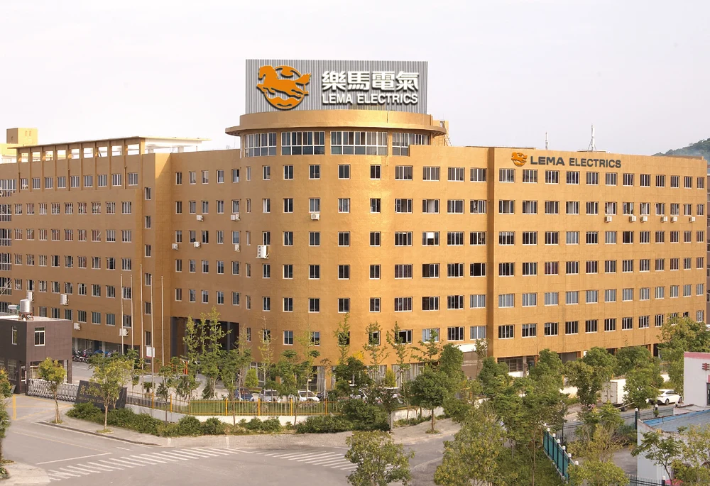
Set up since 2012, our company own the factory, and experienced.

Set up since 2012, our company own the factory, and experienced.

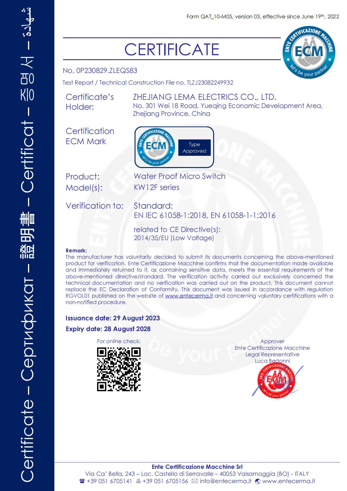
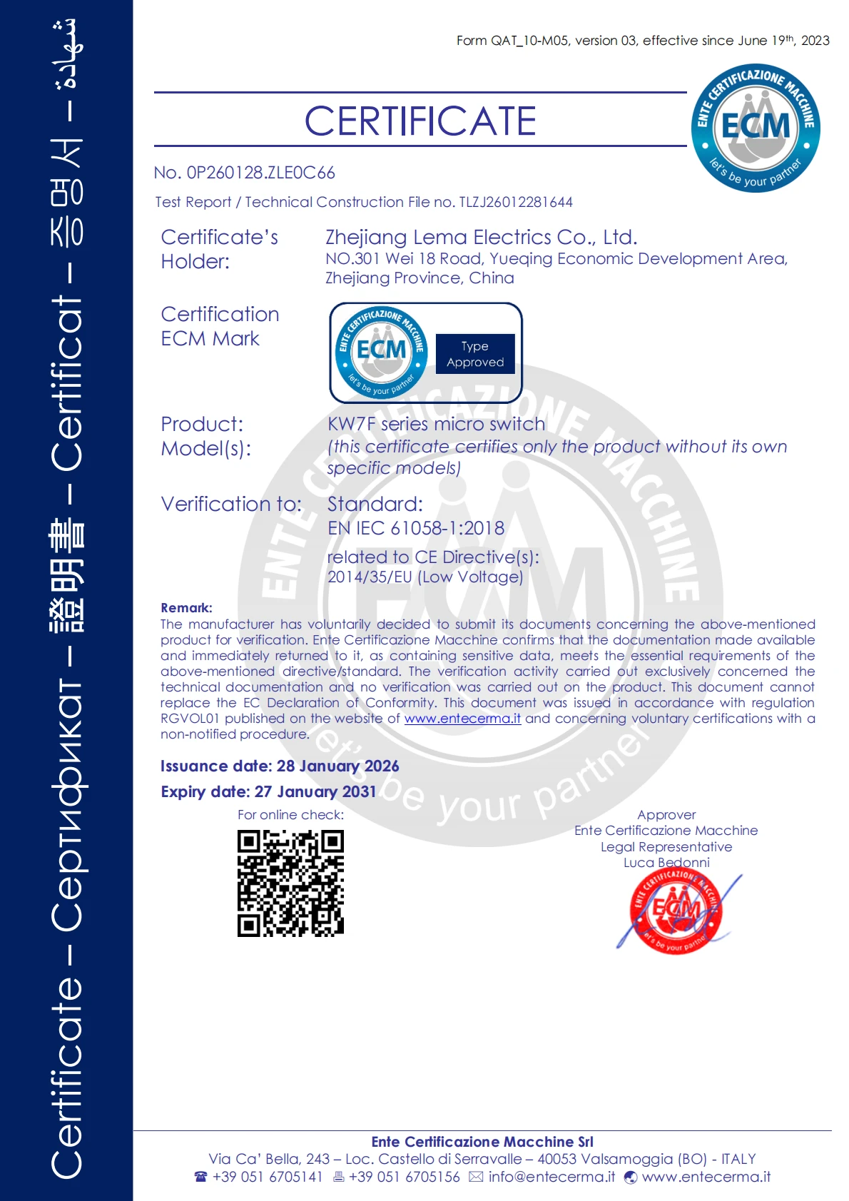
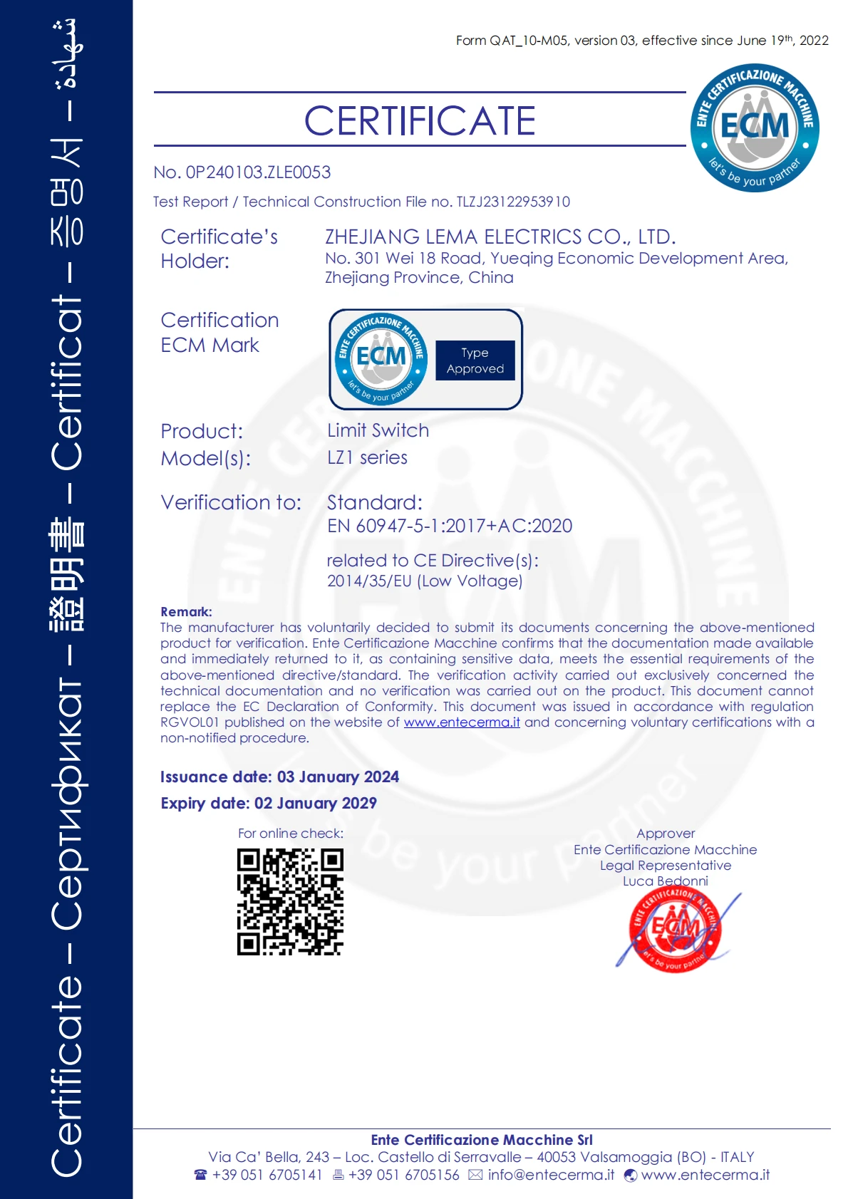
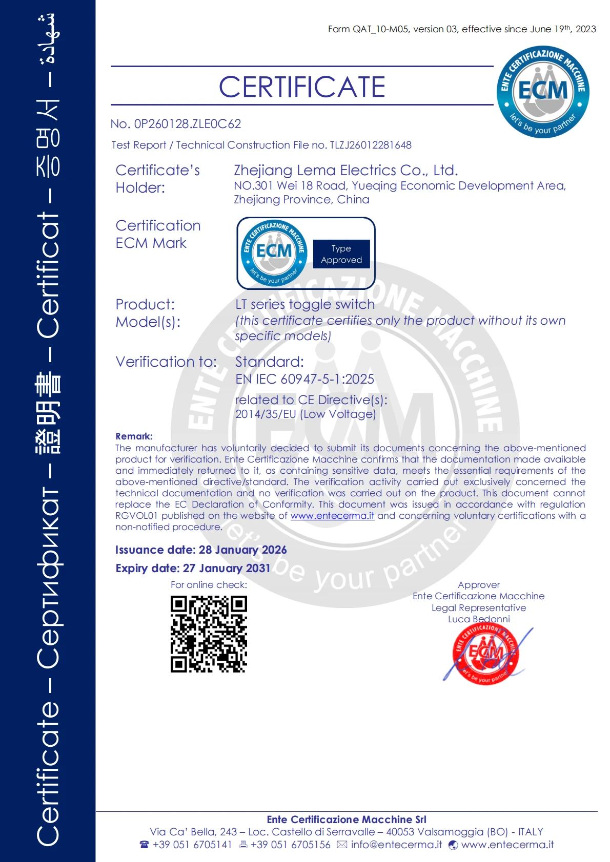
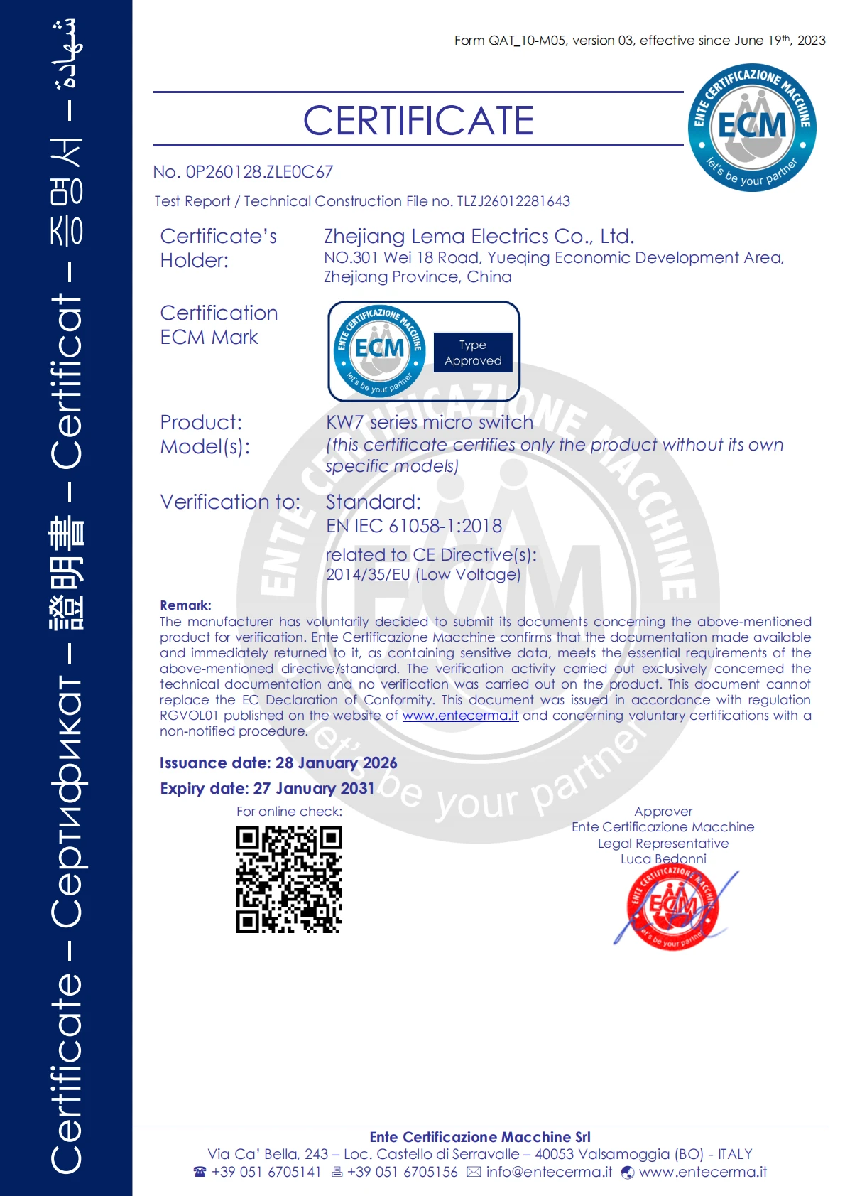
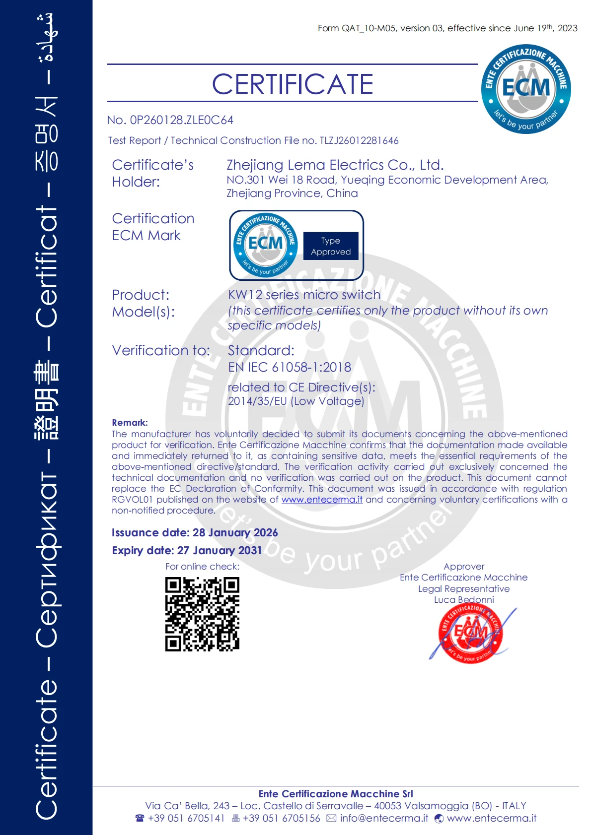
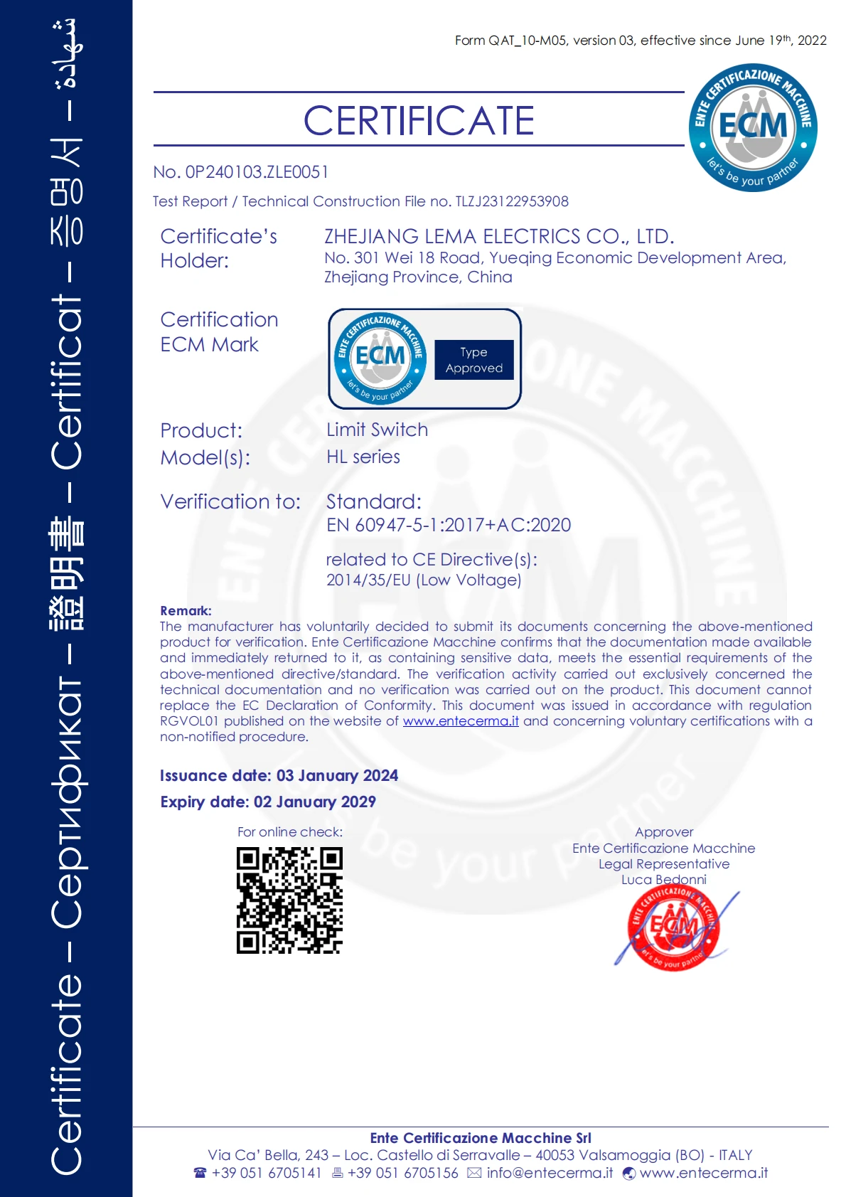
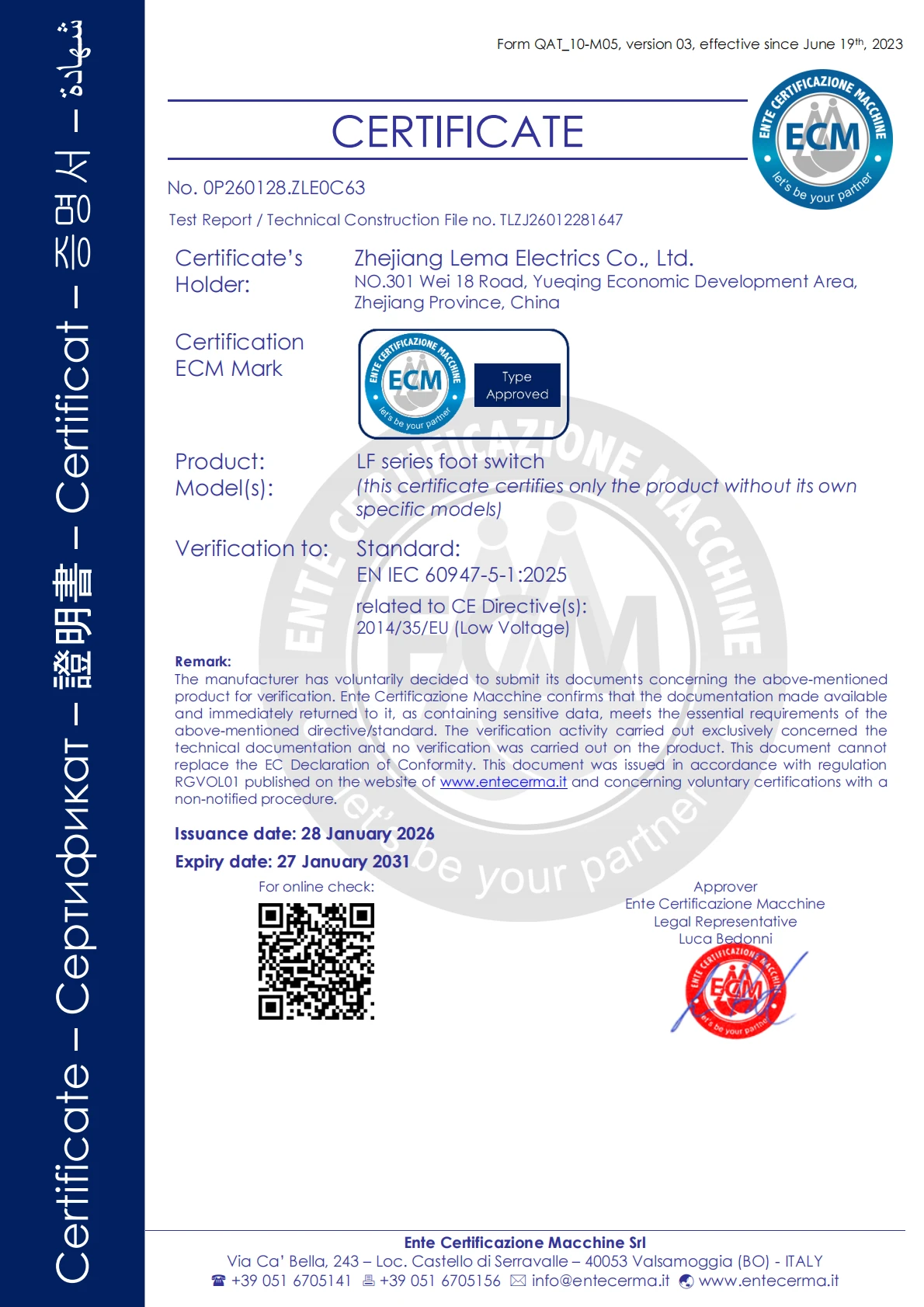
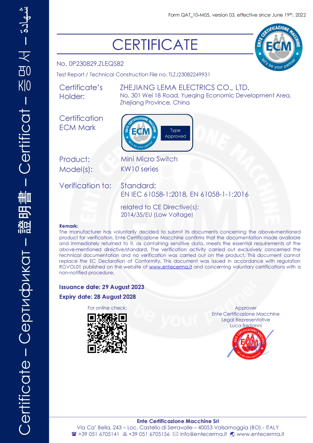
Uiled have obtained relevant CCC, CQC, UL, VDE, CE, ENEC enterprise and relevant product certifications.

We have gained a global sales network reaching many countries over North America, South America, Europe, Africa and South East Asia.

A complete service network has been established to respond to user requests within 24 hours.
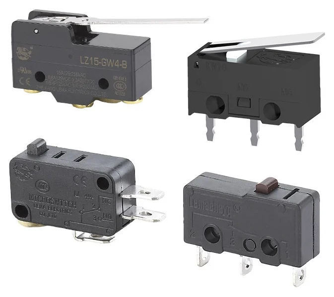
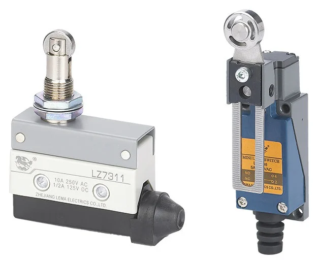
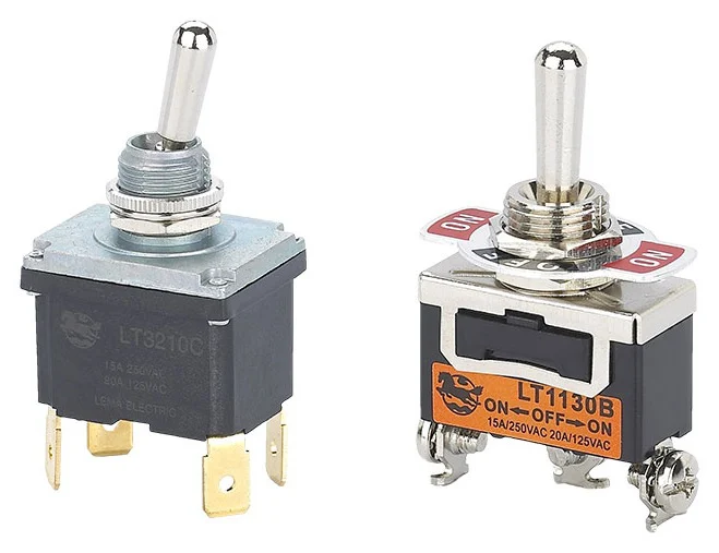
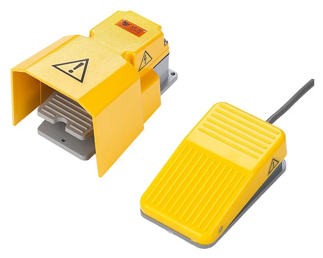
The core products include micro switches and travel limit Switch, push button switch, foot switch, toggle switch, AC power socket.
The core products include micro switches and travel limit Switch, push button switch, foot switch, toggle switch, AC power socket.
VIEW MORE PRODUCTSLema is committed to R&D, production and sales of industrial control electrical switches. The company's core products include micro switches and travel limit Switches, push button switches, foot switches, toggle switches, AC power socket.
After nearly 30 years of steady development, Lema has become a large-scale professional manufacturer of micro switches in China. The company currently covers an area of more than 11,000 square meters.
Established in
Exporting countries and regions
Factory floor area
Authentication certificate
Committed to research and development, production, sales of industrial electrical switches and connectors
Industrial automation empowers smart manufacturing with reduced manual labor, higher precision, and greater efficiency.
VIEW MORE



Customer recognition is our greatest motivation.
Stay updated with the latest developments, product launches, and industry insights.
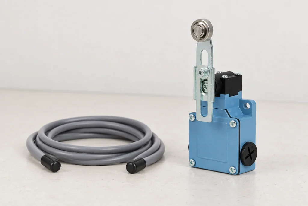
Limit switch cable shielding can help control interference, but it should follow a diagnosis of the complete switch-to-controller circuit. A false PLC transition may come from contact bounce, unstable actuation, a loose connection, incorrect input logic or electrical noise coupled into the cable. Identify the actual cause before changing shield connections. The correct cable route and termination depend on the controller instructions, the installation's bonding arrangement and the interference being addressed. There is no universal rule that every limit-switch shield must be connected at exactly one end. The LEMA LZ1 mechanical limit switch is the product example here. Its enclosure and actuator do not define the shield arrangement of an external cable or prove immunity of a complete PLC installation. The photographs show the intact switch beside separate cable-planning items, with no approved wiring arrangement implied. Use the exact switch terminal record and controller manual when preparing the circuit. Establish what the PLC is actually seeing Write down the unwanted event precisely. Note whether it occurs during switch actuation, while the mechanism is stationary, when a motor starts or during another machine action. Distinguish the PLC's raw input indication from a program condition or a displayed alarm. These observations help determine whether the problem belongs to the physical signal path or to the way the signal is interpreted. Start with the limit switch PLC wiring guide to confirm the intended contact path and input arrangement. Check the actual terminal identities, supply reference and selected input channel against the drawing. A wiring error should not be hidden by adding shielding or software delays. Record the original configuration so any later change can be assessed against a known starting point. Separate mechanical...
↗UL 94 flammability evidence for a power inlet describes the behavior of a specified plastic material under defined test conditions. It does not, by itself, establish the inlet's current rating, operating temperature, insulation performance or approval of the finished equipment. When an OEM specification calls for a particular flame classification, connect that requirement to the actual resin grade, color, thickness and component configuration being supplied. A generic claim that the inlet uses flame-retardant plastic leaves important questions unanswered. This guide uses the LEMA IPZ power socket series as a product example. Its visible black housing establishes neither a resin identity nor a UL 94 classification. The illustrations follow the screw-mount IPZ-4 form shown in the product reference; they are not photographs of a flammability test. Ask LEMA for the material and approval records applicable to the exact ordered configuration before adding a flame-class claim to an equipment specification. Define which part needs the material evidence A power inlet can contain several nonmetallic parts with different functions. Identify the housing, any separate carrier and other relevant insulating parts on the actual construction record. Ask which material specification applies to each part being reviewed. Do not assume that one resin statement covers every plastic item in a wider family or an attached accessory. This identification step also prevents a common document mix-up: a supplier may provide a valid material record for a nearby component rather than the part actually ordered. Tie the response to the manufacturer's complete part number and drawing revision. If the construction is not documented at the level you need, make that a focused supplier question instead of filling the gap with an assumption about appearance. Read UL 94...
↗IP67 vs NEMA 4 limit switch specifications cannot be resolved by treating the two labels as equivalent. They belong to different enclosure classification systems and address different sets of conditions. Identify the actual exposure, check the scope of the rating for the ordered switch, and review the complete installed arrangement. If a purchase specification requires NEMA Type 4, an IP67 statement alone is not enough to approve a substitution. Ask for evidence that answers the original requirement, or obtain a documented engineering decision to revise the requirement. The LEMA LZ1 limit switch is the mechanical product illustrated here. Its current product page states IP66; this article does not relabel it IP67, NEMA Type 4 or Type 4X. The example shows why a buyer needs to read the actual model record instead of transferring a rating from a related family or a similar-looking enclosure. Identify which protection question you are asking Start with the machine location and operating process. Describe dust, rain, spray, cleaning, occasional immersion and any chemical exposure separately. Also record where the switch is mounted and whether its cable entry faces a likely water path. A single word such as waterproof does not communicate these conditions well enough for a supplier to assess the correct configuration. IEC 60529 defines the IP classification framework for enclosure protection. Use the applicable standard and product evidence to interpret a claimed code. An immersion-related designation does not automatically answer every question about water jets, cleaning chemicals, corrosion or a machine's maintenance procedure. Those need their own relevant requirements and evidence. Understand why a conversion chart is only a starting point NEMA's enclosure-type guide expressly limits the direction in which its comparison table...
↗